
 In this installment, I am going to discuss the implementation of the 6502’s status register. In the previous article for the workbench Software Emulating 8-Bit Memory for the 6502 , I discussed a simple memory model using the Python language. There are lots of little scripting components that are required before we can do anything basic with the 6502 emulator that’s being created. I have been playing with numerous things on the virtual workbench. I have improved upon the memory code presented earlier. I have the basics of machine language monitor running. The machine language monitor just dumps memory right now. It’s not very useful at this point for anything. It's a far cry from the desired NES game development and Atari hacking emulator. But the brains are starting to take shape!
What I need to do before I can move on with the machine language monitor implementation is start piecing together a bare bones virtual 6502 Microprocessor Unit (MPU). The coding of the registers is simple and straight forward. But before I can use any of these registers, many of the 6502’s decision making for handling operations is based on its processor status register. The compilation of my research on the 6502 status register comes from online archived articles and wikis, All About the Status Register – Compute! Magazine 1984, 6502 Microprocessor info –NESDev, Synertek 6502 Programming Manual, and Synertek 6502 Hardware Manual. I have a lot of other sources, but the Synertek Programming Manual is my road map.
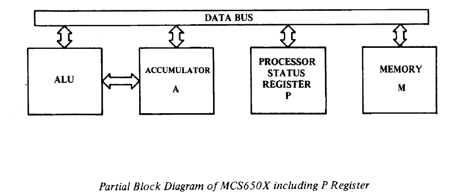
The 6502’s processor status register, sometimes called the P-register, or SR (status register), in hardware programming guides, is an 8-bit register used for assisting the processor in making decisions on the behaviors of registers.
Each of the 8-bits is a 1-bit binary flag. When the bit value is 1 the flag is set, and when the bit is zero, the flag is clear. The breakdown of these bits in the Processor Status Register is depicted in the following figure.

The bit flags are ordered from 0 – 7 in the register in this manner (source).

Carry Flag
The rightmost bit, 0, is the 6502’s carry flag. This gets set when arithmetic operation results are greater than 255. Remember this is an 8-bit processor. The carry flag is used for binary arithmetic for borrowing and carrying operations and for shift and rotate operations rolling over into a 9th bit (we’re only 8-bit.Zero Flag
Bit 1 is the zero flag. When the result of any arithmetic or logical operation is zero this flag is set (=1). When the results are non-zero the flag is cleared (=0). This is a read only bit.Interrupt Disable Flag
Bit 2 is the interrupt disable flag. Sometimes the processor operation needs to be interrupted to handle activity outside the processor, such as processing keyboard strokes. When this flag is set (=1), maskable interrupts are not allowed.Decimal Mode Flag
Bit 3 is the decimal mode flag. The 6502 only natively speaks binary, based 2 number system. To use decimal, the 6502 needs to be put into Binary Coded Decimal mode. BCD mode is set by the 6502 instruction SED.Break Flag
Bit 4 is the break flag, set by the 6502 instruction BRK.Unused
Bit 5 is intentionally left unused.Overflow Flag
Bit 6 is the overflow flag, which is used to track sign change in signed binary arithmetic. No instruction sets this flag. The 6502 instruction CLV clears this flag.Negative Flag
Bit 7 is the negative flag, which is set when the result of an operation is negative. Often involves operations using signed numbers. No instructions set or clear this flag. Merely used for sign testing purposes.That’s it for the breakdown of the 8-bits in the processor status register.
Now to emulate these TTL flipflops in Python code. Remember this is off my workbench and things are in flux. So this is what my code snapshot looks like. I will clean this up as it evolves and place the entire project in github. For now, it's still coming together and you can see the emulator take shape.
Here is the current Python source code for the processor status register emulation.
1:  #-------------------------------------------------------------------------------
2:  # Name:    MPU_6502py
3:  # Purpose:   6502 MPU emulation library
4:  #
5:  # Author:    Michael Norton
6:  #
7:  # Created:   05/20/2016
8:  #
9:  #        07/13/2016 Implement processor status register
10:  #                   Implement processor addressing format
11:  #
12:  # Copyright:  (c) Michael Norton Black Hole Computing 2016
13:  #
14:  #-------------------------------------------------------------------------------
15:  #--------------------------------------------------------#
16:  #                Processor Status Register               #
17:  #--------------------------------------------------------#
18:  # notes: http://www.atarimagazines.com/compute/issue53/047_1_All_About_The_Status_Register.php
19:  # notes: http://www.atarimagazines.com/compute/issue54/150_1_All_About_The_Status_Register.php
20:  # notes: http://nesdev.com/6502.txt
21:  # * THE STATUS REGISTER
22:  #
23:  # These bits are described below:
24:  #
25:  #   Bit No.    7  6  5  4  3  2  1  0
26:  #               S  V    B  D  I  Z  C
27:  #
28:  # Processor status register flag bit field assignments
29:  C_Status_bit = 0b1          # Carry flag bit 0: set = bin(1) b0000 0001
30:  Z_Status_bit = 0b10         # Zero flag bit 1: set = bin(2) b0000 0010
31:  I_Status_bit = 0b100        # Interrupt bit 2: set = bin(4) b0000 0100
32:  D_Status_bit = 0b1000       # BCD flag  bit 3: set = bin(8) b0000 1000
33:  B_Status_bit = 0b10000      # BRK flag  bit 4: set = bin(16) b0001 0000
34:  U_Status_bit = 0b100000     # Not used  bit 5: set = bin(32) b0010 0000
35:  V_Status_bit = 0b1000000    # OVRFL flag bit 6: set = bin(64) b0100 0000
36:  S_Status_bit = 0b10000000   # Sign flag bit 7: set = bin(128) b1000 0000
37:  #
38:  # setting the processor status register:
39:  # PROCESSOR_STATUS_REGISTER &= ~(C_Status_bit | S_Status_bit | Z_Status_bit)
40:  #
41:  # intialize the processor status register
42:  PROCESSOR_STATUS_REGISTER = B_Status_bit | U_Status_bit
43:  def set_Processor_Status_Bits( status_bits):
44:    global PROCESSOR_STATUS_REGISTER
45:    PROCESSOR_STATUS_REGISTER = PROCESSOR_STATUS_REGISTER | status_bits
46:    return
47:  # function: clear_Processor_Status_Bits( status_bits)
48:  #
49:  #   100000010000 # status
50:  #  &      ~10000 # ~FLAG
51:  #  -----------------------
52:  #  = 100000000000 # new status
53:  #
54:  def clear_Processor_Status_Bits( status_bits):
55:    global PROCESSOR_STATUS_REGISTER
56:    PROCESSOR_STATUS_REGISTER &= ~status_bits
57:    return
58:  def get_Processor_Status_Bits():
59:    global PROCESSOR_STATUS_REGISTER
60:    return PROCESSOR_STATUS_REGISTER
Here is my code driver for the test.
1:  #-------------------------------------------------------------------------------
2:  # Name:    MPUTest.py
3:  # Purpose:   Software driver for MPU_6502.py
4:  #
5:  # Author:   Michael Norton
6:  #
7:  # Created:   05/20/2016
8:  # Copyright:  Copyright: (c) Michael Norton Black Hole Computing 2016
9:  #
10:  #-------------------------------------------------------------------------------
11:  # import 6502 library module
12:  from MPU_6502 import *
13:  def main():
14:    set_Processor_Status_Bits(C_Status_bit)
15:    print ("Debug Status Register:", bin(get_Processor_Status_Bits()))
16:    clear_Processor_Status_Bits(C_Status_bit)
17:    print ("Debug Status Register:", bin(get_Processor_Status_Bits()))
18:  if __name__ == '__main__':
19:    main()
Executing the code you will see the bits toggling, which is the result we want. We will need the processor status emulation for scripting the general purpose registers on our software emulated 6502.
1:  Debug Status Register: 0b110000
2:  Debug Status Register: 0b110001
3:  Debug Status Register: 0b110000
4:  >>>
That's enough for now. This is the basic code we need to emulate the 6502 MPU's processor status register. The emulator is slowly taking shape!! Until next time...


