Saturday, July 23, 2016

Displaying the 6502 MPU Register States


Displaying the 6502 MPU Register States

Moving slowly along in the summer of coding project, an emulated 6502 MPU written in the Python 3.5 scripting language. As the project is taking shape, I am moving some cleaned up scripts into libraries. One great convenience I have found in this project is the overGrive for Raspberry Pi systems. This software sets up a Google Drive on your Raspberry Pi desktop. I found this to be advantageous since I can code anywhere on any platform I have Internet connectivity and Google Drive access. On the ride into the city of San Francisco I can code on my old iPad 2, using the amazing Pythonista, or at home on my mac or my  Raspberry Pi. My goal is to write platform independent code for the 6502 MPU emulator software. On my Raspberry Pi desktop, the Google Drive appears as a folder and is accessible as a folder.

Python Source Directory on Google Drive


That's pretty much how I setup my development sandbox. I tend to spend a lot of time on the iPad 2, coding in Pythonista, which is great. I am BETA testing the Python 3.5 release for that now. The big hangup is that the iPad is clunky for coding. But when you're mobile and you need to code that's perfect. The source code on Google Drive has allowed me to code essentially everywhere I have network connectivity. For the Raspberry Pi it's been a huge bonus. The only downfall to the OverGrive is that it seems to take minutes to automatically update where Google Drive on the Mac and iPad are seemingly instantaneous. But we're all in the development stages in all of this stuff. So I hope this gets resolved soon on the Raspberry Pi OverGrive release.

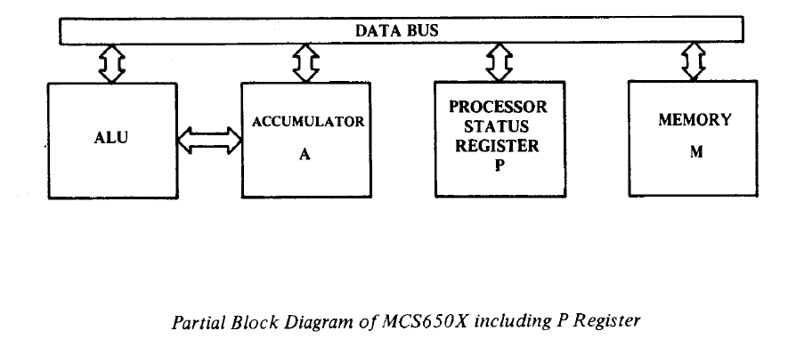
Now to the current task at hand. Last entry, Software Emulating the 6502 Status Register, I explained the Python code I implemented to toggle the bits in the Processor Status Register. This is essentially an 8-bit register that contains 7 individual binary flags on operation states of the 6502 register. With the bits toggling I needed to write some code to display the individual bits for debug purposes. And from that effort I found myself writing the code to display the current values in all the registers of the 6502 MPU. This was another crucial tool needed in developing the Machine Language monitor and displaying the register contents at every cycle step for debugging purposes. So here goes. Let's take a look at the Processor Status Register (commonly referred to as the SR, and sometimes called the P register) tool for displaying the state of this register.

Displaying the SR State

In other Python 6502 emulators, I have seen developers choose to create individual flags for all 7 states (see my last article,  Software Emulating the 6502 Status Register). I choose to keep the SR register as designed and just toggle bits in the register, just like the real McCoy. A quick refresher from last time, I can set, get, and clear bits in the Sr.


>>> bin (get_Processor_Status_Bits())
'0b110000'
>>> 

What I need for the machine language monitor is a formatted output to tell me what flags are being set. This is the formatted processor output tool I developed.


>>> print( get_Format_Processor_Status_Bits_Output() )
NV-BDIZC
00110000
>>> 

What was initially a headache and failure of testing various snippets, the code actually emerged as a simple few lines of code. There are more comments then lines of code.


 1
 2
 3
 4
 5
 6
 7
 8
 9
10
11
12
13
14
15
16
17
18
19
20
21
22
23
# function: get_format_processor_status_bits_output
#
# Retrieves the current flags in the processor
# status register and returns binary flags of
# the current bits set as STRING for
# formatted output to console.
#
# Arguments: none
#
# Returns: String
#
# Example Usage:
#
# >>> print( get_Format_Processor_Status_Bits_Output() )
# NV-BDIZC
# 00110000
# >>> 
#
def get_Format_Processor_Status_Bits_Output():
    
    # get the processor status register bits
    sr_bits = get_Processor_Status_Bits()
    return ("NV-BDIZC\n%s" % format(sr_bits,'08b') )

Note: the Python format command, with argument '08b' passed in strips the "0b" from the Python string, so all we see are the bits. This is the magic helper of this operation. The results are the bits are perfectly aligned to their corresponding bit flags. Now with this little confidence builder, I moved on to tackle a similar problem, but display the status of all the registers. This would come in handy as the machine language monitor takes shape and we start stepping through machine code instructions.

Displaying the 6502 Current Register States

Interesting enough, to this point I haven't really coded any of the registers (except for the SR) for the 6502 emulator. I have been writing a lot of preparatory source code. The time has come for adding the general purpose registers.

The 6502 MPU Registers

As I developed this code, I completely have the future goal in mind of writing the ML monitor as well. I found a nice formatted output from a classic book, Machine Language for Beginners, at the Atari Archive site. This is an online copy of the classic book. I think I still have a copy in storage at my parents house.  Anyhow, my vision for formatted output comes from this book.

Program 4-1. Current Status Of The Registers.

  PC  IRQ  SR AC XR YR SP
 0005 E455 30 00 5E 04 F8


What evolved in my code, is this formatted output from that example. I initialized my emulated registers with the same values, since they weren't really doing anything yet.


 1
 2
 3
 4
 5
 6
 7
 8
 9
10
11
12
13
14
15
16
#--------------------------------------------------------#
#                    6502 MPU Registers                  #
#--------------------------------------------------------#

# notes: http://www.atariarchives.org/mlb/chapter4.php
#
#
#  PC  IRQ  SR AC XR YR SP
# 0005 E455 30 00 5E 04 F8
#

AC = 0x0      # Accumulator         8-bt
XR = 0x5E     # X index register    8-bit
YR = 0X04     # Y index register    8-bit
SP = 0XF8     # Stack Pointer       8-bit
IRQ = 0xE455  # Interrupt Request  16-bit

Now I have something to display with my register state code. With Python, the formatted output code for this is fairly straight forward and very simple.


 1
 2
 3
 4
 5
 6
 7
 8
 9
10
11
12
13
14
15
16
17
18
19
20
21
22
23
# function: format_Register_States_Output()
#
# Display the 6502 MPU register states.
# The desired output is modelled after the machine
# language output display for found in the book,
# Machine Language for Beginners.
# http://www.atariarchives.org/mlb/chapter4.php
# Program 4-1. Current Status of the Registers
#
#  PC  IRQ  SR AC XR YR SP
# 0005 E455 30 00 5E 04 F8
#
# Arguments: none
#
# Returns: formatted string  - displays the 6502 MPU register states
#
def format_Register_States_Output():
    global AC, XR,YR, SP, PC, IRQ

    # get the processor status register bits
    sr_bits = get_Processor_Status_Bits()

    return ("PC   IRQ  AC XR YR SP SR NV-BDIZC\n%04x %04x %02x %02x %02x %02x %02x %s") % (PC, IRQ, AC, XR, YR, SP, sr_bits, format(sr_bits,'08b'))

This is still a lot of dirty code on the workbench I want to clean up. But you're starting to get the idea of where I am going with this code. This function provides us with the following output.


>>> print(format_Register_States_Output())
PC   IRQ  AC XR YR SP SR NV-BDIZC
008d e455 00 5e 04 f8 30 00110000
>>> 

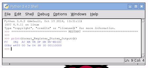
Sample Output on Raspberry Pi Python 3.4.2 Console

Which is the beginnings of a dev tool to implement in a machine language monitor. We can use this function to step through each cycle in the emulated 6502 MPU.

Were slowly making progress. But that's what is on my Raspberry Pi workbench and development IDE for Saturday July 23, 2016. As the code starts to take shape further I will move this out to a github repository. The DIY Atari and NES Hacking Emulator are becoming more of a reality now. Until next time... Happy Hacking!


Friday, July 15, 2016

Software Emulating the 6502 Status Register

In this installment, I am going to discuss the implementation of the 6502’s status register. In the previous article for the workbench Software Emulating 8-Bit Memory for the 6502 , I discussed a simple memory model using the Python language. There are lots of little scripting components that are required before we can do anything basic with the 6502 emulator that’s being created. I have been playing with numerous things on the virtual workbench. I have improved upon the memory code presented earlier. I have the basics of machine language monitor running. The machine language monitor just dumps memory right now. It’s not very useful at this point for anything. It's a far cry from the desired NES game development and Atari hacking emulator. But the brains are starting to take shape!

What I need to do before I can move on with the machine language monitor implementation is start piecing together a bare bones virtual 6502 Microprocessor Unit (MPU). The coding of the registers is simple and straight forward. But before I can use any of these registers, many of the 6502’s decision making for handling operations is based on its processor status register. The compilation of my research on the 6502 status register comes from online archived articles and wikis, All About the Status Register – Compute! Magazine 1984, 6502 Microprocessor info –NESDev, Synertek 6502 Programming Manual, and Synertek 6502 Hardware Manual. I have a lot of other sources, but the Synertek Programming Manual is my road map.

The 6502’s processor status register, sometimes called the P-register, or SR (status register), in hardware programming guides, is an 8-bit register used for assisting the processor in making decisions on the behaviors of registers.


Each of the 8-bits is a 1-bit binary flag. When the bit value is 1 the flag is set, and when the bit is zero, the flag is clear. The breakdown of these bits in the Processor Status Register is depicted in the following figure.


The bit flags are ordered from 0 – 7 in the register in this manner (source).


Carry Flag

The rightmost bit, 0, is the 6502’s carry flag. This gets set when arithmetic operation results are greater than 255. Remember this is an 8-bit processor. The carry flag is used for binary arithmetic for borrowing and carrying operations and for shift and rotate operations rolling over into a 9th bit (we’re only 8-bit.

Zero Flag

Bit 1 is the zero flag. When the result of any arithmetic or logical operation is zero this flag is set (=1). When the results are non-zero the flag is cleared (=0). This is a read only bit.

Interrupt Disable Flag

Bit 2 is the interrupt disable flag. Sometimes the processor operation needs to be interrupted to handle activity outside the processor, such as processing keyboard strokes. When this flag is set (=1), maskable interrupts are not allowed.

Decimal Mode Flag

Bit 3 is the decimal mode flag. The 6502 only natively speaks binary, based 2 number system.  To use decimal, the 6502 needs to be put into Binary Coded Decimal mode. BCD mode is set by the 6502 instruction SED.

Break Flag

Bit 4 is the break flag, set by the 6502 instruction BRK.

Unused

Bit 5 is intentionally left unused.

Overflow Flag

Bit 6 is the overflow flag, which is used to track sign change in signed binary arithmetic. No instruction sets this flag. The 6502 instruction CLV clears this flag.

Negative Flag

Bit 7 is the negative flag, which is set when the result of an operation is negative. Often involves operations using signed numbers. No instructions set or clear this flag. Merely used for sign testing purposes.
That’s it for the breakdown of the 8-bits in the processor status register. 

Now to emulate these TTL flipflops in Python code. Remember this is off my workbench and things are in flux. So this is what my code snapshot looks like. I will clean this up as it evolves and place the entire project in github. For now, it's still coming together and you can see the emulator take shape.

Here is the current Python source code for the processor status register emulation.


1:  #-------------------------------------------------------------------------------  
2:  # Name:    MPU_6502py  
3:  # Purpose:   6502 MPU emulation library  
4:  #  
5:  # Author:    Michael Norton  
6:  #  
7:  # Created:   05/20/2016  
8:  #  
9:  #        07/13/2016 Implement processor status register  
10:  #                   Implement processor addressing format  
11:  #  
12:  # Copyright:  (c) Michael Norton Black Hole Computing 2016  
13:  #  
14:  #-------------------------------------------------------------------------------  
15:  #--------------------------------------------------------#  
16:  #                Processor Status Register               #  
17:  #--------------------------------------------------------#  
18:  # notes: http://www.atarimagazines.com/compute/issue53/047_1_All_About_The_Status_Register.php  
19:  # notes: http://www.atarimagazines.com/compute/issue54/150_1_All_About_The_Status_Register.php  
20:  # notes: http://nesdev.com/6502.txt  
21:  # * THE STATUS REGISTER  
22:  #  
23:  # These bits are described below:  
24:  #  
25:  #   Bit No.    7  6  5  4  3  2  1  0  
26:  #               S  V    B  D  I  Z  C  
27:  #  
28:  # Processor status register flag bit field assignments  
29:  C_Status_bit = 0b1          # Carry flag bit 0: set = bin(1) b0000 0001  
30:  Z_Status_bit = 0b10         # Zero flag bit 1: set = bin(2) b0000 0010  
31:  I_Status_bit = 0b100        # Interrupt bit 2: set = bin(4) b0000 0100  
32:  D_Status_bit = 0b1000       # BCD flag  bit 3: set = bin(8) b0000 1000  
33:  B_Status_bit = 0b10000      # BRK flag  bit 4: set = bin(16) b0001 0000  
34:  U_Status_bit = 0b100000     # Not used  bit 5: set = bin(32) b0010 0000  
35:  V_Status_bit = 0b1000000    # OVRFL flag bit 6: set = bin(64) b0100 0000  
36:  S_Status_bit = 0b10000000   # Sign flag bit 7: set = bin(128) b1000 0000  
37:  #  
38:  # setting the processor status register:  
39:  # PROCESSOR_STATUS_REGISTER &= ~(C_Status_bit | S_Status_bit | Z_Status_bit)  
40:  #  
41:  # intialize the processor status register  
42:  PROCESSOR_STATUS_REGISTER = B_Status_bit | U_Status_bit  
43:  def set_Processor_Status_Bits( status_bits):  
44:    global PROCESSOR_STATUS_REGISTER  
45:    PROCESSOR_STATUS_REGISTER = PROCESSOR_STATUS_REGISTER | status_bits  
46:    return  
47:  # function: clear_Processor_Status_Bits( status_bits)  
48:  #  
49:  #   100000010000 # status  
50:  #  &      ~10000 # ~FLAG  
51:  #  -----------------------  
52:  #  = 100000000000 # new status  
53:  #  
54:  def clear_Processor_Status_Bits( status_bits):  
55:    global PROCESSOR_STATUS_REGISTER  
56:    PROCESSOR_STATUS_REGISTER &= ~status_bits  
57:    return  
58:  def get_Processor_Status_Bits():  
59:    global PROCESSOR_STATUS_REGISTER  
60:    return PROCESSOR_STATUS_REGISTER  

Here is my code driver for the test.


1:  #-------------------------------------------------------------------------------  
2:  # Name:    MPUTest.py  
3:  # Purpose:   Software driver for MPU_6502.py  
4:  #  
5:  # Author:   Michael Norton  
6:  #  
7:  # Created:   05/20/2016  
8:  # Copyright:  Copyright: (c) Michael Norton Black Hole Computing 2016   
9:  #   
10:  #-------------------------------------------------------------------------------  
11:  # import 6502 library module  
12:  from MPU_6502 import *  
13:  def main():  
14:    set_Processor_Status_Bits(C_Status_bit)  
15:    print ("Debug Status Register:", bin(get_Processor_Status_Bits()))  
16:    clear_Processor_Status_Bits(C_Status_bit)  
17:    print ("Debug Status Register:", bin(get_Processor_Status_Bits()))  
18:  if __name__ == '__main__':  
19:    main()  


Executing the code you will see the bits toggling, which is the result we want. We will need the processor status emulation for scripting the general purpose registers on our software emulated 6502.


1:  Debug Status Register: 0b110000  
2:  Debug Status Register: 0b110001  
3:  Debug Status Register: 0b110000  
4:  >>>   

That's enough for now. This is the basic code we need to emulate the 6502 MPU's processor status register. The emulator is slowly taking shape!! Until next time...