Sunday, August 21, 2016

The Raspberry PI Terminal Server

When I bought my Raspberry Pi a year ago I had no idea the little computer that could would literally become a hobby platform as well as my go to workhorse. Because of its size, I have a raspberry pi that is a terminal and browser interface to my ASUS router. Now when the ol' homestead network expansion required a Cisco 2960 front end switch, it was time to expand the horizons of the pi.

After a quick search on google, I found the software of choice for this operation is ser2net (see Raspberry PI as Cisco Console). It's a good article on setting up the pi as a terminal server. I am going to give the quick low down of how I installed the ser2net software and how I brought up my switch using the pi as a terminal server. You will need a USB to 9-pin serial cable to connect to the blue 9-pin serial cable that comes with all Cisco networking hardware. I had one of these cables laying around from my days as an employee with Cisco (days of long gone that is...). The picture below shows my simple network setup.


Step 1. Install the software.

Login to your raspberry pi and open a terminal window. Install the ser2net software package.

 sudo apt-get install ser2net  

When the install is completed you will need configure the banner and the usb0 port command. I copied and pasted the details from Raspberry PI as a Cisco Console. But slightly tweaked the banner for my network use.

 sudo vi /etc/ser2net.conf  

Insert the configuration for your banner header and your usb0 port information.

 # BANNER:banner:\r\nser2net port \p device \d [\s] (Debian GNU/Linux)\r\n\r\n  
 BANNER:banner:Skynet Terminal Server TCP port p device d rn  
 2000:telnet:600:/dev/ttyS0:9600 8DATABITS NONE 1STOPBIT banner  
 2001:telnet:600:/dev/ttyS1:9600 8DATABITS NONE 1STOPBIT banner  
 3000:telnet:600:/dev/ttyS0:19200 8DATABITS NONE 1STOPBIT banner  
 3001:telnet:600:/dev/ttyS1:19200 8DATABITS NONE 1STOPBIT banner  
 4001:telnet:0:/dev/ttyUSB0:9600 8DATABITS NONE 1STOPBIT banner  

That's it for the configuration. Pretty painless, huh?

Step 2. Fire in the Hole!

Open a new terminal on your raspberry pi and execute the ser2net software package.

 ser2net -n  

Open a new terminal window and open a telnet session using the port number to the Cisco device. For laughs I logged in from my mac to see if everything was in place for the terminal server.
From a terminal window on my Mac I executed a connection request.

 telnet 10.0.0.22 4001  

The log in results to the switch looked like this.

 Last login: Sun Aug 21 15:36:40 on ttys001  
 TheM5:~ daystrum$ telnet 10.0.0.22 4001  
 Trying 192.168.1.201...  
 Connected to raspberrypi.  
 Escape character is '^]'.  
 Skynet Terminal Server TCP port p device d rn  
 Would you like to terminate autoinstall? [yes]: no  
      --- System Configuration Dialog ---  
 Would you like to enter the initial configuration dialog? [yes/no]: no  
 Would you like to terminate autoinstall? [yes]:   
 Switch>  
 00:35:02: %LINK-5-CHANGED: Interface Vlan1, changed state to administratively down  
 Switch>  
 Switch>en  
 Switch#  

That's all there is to it. Down the road I would love to start writing a Python library similar to what we had with TCL and csccon back in the golden era days of Cisco. Again, days of long ago...
 
The Raspberry Pi is an amazing little device. I know this was a brief interruption in discussing a 6502 MPU emulator. But like I said, the Raspberry Pi is an incredible little workhorse. And this is the Raspberry Pi Workbench blog, whatever is on the workbench that is of interest I put on the blog. Hope this helps others out there trying to setup a terminal server for their home, corporate, educational, or certification network.   Until next time....

Saturday, July 23, 2016

Displaying the 6502 MPU Register States


Displaying the 6502 MPU Register States

Moving slowly along in the summer of coding project, an emulated 6502 MPU written in the Python 3.5 scripting language. As the project is taking shape, I am moving some cleaned up scripts into libraries. One great convenience I have found in this project is the overGrive for Raspberry Pi systems. This software sets up a Google Drive on your Raspberry Pi desktop. I found this to be advantageous since I can code anywhere on any platform I have Internet connectivity and Google Drive access. On the ride into the city of San Francisco I can code on my old iPad 2, using the amazing Pythonista, or at home on my mac or my  Raspberry Pi. My goal is to write platform independent code for the 6502 MPU emulator software. On my Raspberry Pi desktop, the Google Drive appears as a folder and is accessible as a folder.

Python Source Directory on Google Drive


That's pretty much how I setup my development sandbox. I tend to spend a lot of time on the iPad 2, coding in Pythonista, which is great. I am BETA testing the Python 3.5 release for that now. The big hangup is that the iPad is clunky for coding. But when you're mobile and you need to code that's perfect. The source code on Google Drive has allowed me to code essentially everywhere I have network connectivity. For the Raspberry Pi it's been a huge bonus. The only downfall to the OverGrive is that it seems to take minutes to automatically update where Google Drive on the Mac and iPad are seemingly instantaneous. But we're all in the development stages in all of this stuff. So I hope this gets resolved soon on the Raspberry Pi OverGrive release.

Now to the current task at hand. Last entry, Software Emulating the 6502 Status Register, I explained the Python code I implemented to toggle the bits in the Processor Status Register. This is essentially an 8-bit register that contains 7 individual binary flags on operation states of the 6502 register. With the bits toggling I needed to write some code to display the individual bits for debug purposes. And from that effort I found myself writing the code to display the current values in all the registers of the 6502 MPU. This was another crucial tool needed in developing the Machine Language monitor and displaying the register contents at every cycle step for debugging purposes. So here goes. Let's take a look at the Processor Status Register (commonly referred to as the SR, and sometimes called the P register) tool for displaying the state of this register.

Displaying the SR State

In other Python 6502 emulators, I have seen developers choose to create individual flags for all 7 states (see my last article,  Software Emulating the 6502 Status Register). I choose to keep the SR register as designed and just toggle bits in the register, just like the real McCoy. A quick refresher from last time, I can set, get, and clear bits in the Sr.


>>> bin (get_Processor_Status_Bits())
'0b110000'
>>> 

What I need for the machine language monitor is a formatted output to tell me what flags are being set. This is the formatted processor output tool I developed.


>>> print( get_Format_Processor_Status_Bits_Output() )
NV-BDIZC
00110000
>>> 

What was initially a headache and failure of testing various snippets, the code actually emerged as a simple few lines of code. There are more comments then lines of code.


 1
 2
 3
 4
 5
 6
 7
 8
 9
10
11
12
13
14
15
16
17
18
19
20
21
22
23
# function: get_format_processor_status_bits_output
#
# Retrieves the current flags in the processor
# status register and returns binary flags of
# the current bits set as STRING for
# formatted output to console.
#
# Arguments: none
#
# Returns: String
#
# Example Usage:
#
# >>> print( get_Format_Processor_Status_Bits_Output() )
# NV-BDIZC
# 00110000
# >>> 
#
def get_Format_Processor_Status_Bits_Output():
    
    # get the processor status register bits
    sr_bits = get_Processor_Status_Bits()
    return ("NV-BDIZC\n%s" % format(sr_bits,'08b') )

Note: the Python format command, with argument '08b' passed in strips the "0b" from the Python string, so all we see are the bits. This is the magic helper of this operation. The results are the bits are perfectly aligned to their corresponding bit flags. Now with this little confidence builder, I moved on to tackle a similar problem, but display the status of all the registers. This would come in handy as the machine language monitor takes shape and we start stepping through machine code instructions.

Displaying the 6502 Current Register States

Interesting enough, to this point I haven't really coded any of the registers (except for the SR) for the 6502 emulator. I have been writing a lot of preparatory source code. The time has come for adding the general purpose registers.

The 6502 MPU Registers

As I developed this code, I completely have the future goal in mind of writing the ML monitor as well. I found a nice formatted output from a classic book, Machine Language for Beginners, at the Atari Archive site. This is an online copy of the classic book. I think I still have a copy in storage at my parents house.  Anyhow, my vision for formatted output comes from this book.

Program 4-1. Current Status Of The Registers.

  PC  IRQ  SR AC XR YR SP
 0005 E455 30 00 5E 04 F8


What evolved in my code, is this formatted output from that example. I initialized my emulated registers with the same values, since they weren't really doing anything yet.


 1
 2
 3
 4
 5
 6
 7
 8
 9
10
11
12
13
14
15
16
#--------------------------------------------------------#
#                    6502 MPU Registers                  #
#--------------------------------------------------------#

# notes: http://www.atariarchives.org/mlb/chapter4.php
#
#
#  PC  IRQ  SR AC XR YR SP
# 0005 E455 30 00 5E 04 F8
#

AC = 0x0      # Accumulator         8-bt
XR = 0x5E     # X index register    8-bit
YR = 0X04     # Y index register    8-bit
SP = 0XF8     # Stack Pointer       8-bit
IRQ = 0xE455  # Interrupt Request  16-bit

Now I have something to display with my register state code. With Python, the formatted output code for this is fairly straight forward and very simple.


 1
 2
 3
 4
 5
 6
 7
 8
 9
10
11
12
13
14
15
16
17
18
19
20
21
22
23
# function: format_Register_States_Output()
#
# Display the 6502 MPU register states.
# The desired output is modelled after the machine
# language output display for found in the book,
# Machine Language for Beginners.
# http://www.atariarchives.org/mlb/chapter4.php
# Program 4-1. Current Status of the Registers
#
#  PC  IRQ  SR AC XR YR SP
# 0005 E455 30 00 5E 04 F8
#
# Arguments: none
#
# Returns: formatted string  - displays the 6502 MPU register states
#
def format_Register_States_Output():
    global AC, XR,YR, SP, PC, IRQ

    # get the processor status register bits
    sr_bits = get_Processor_Status_Bits()

    return ("PC   IRQ  AC XR YR SP SR NV-BDIZC\n%04x %04x %02x %02x %02x %02x %02x %s") % (PC, IRQ, AC, XR, YR, SP, sr_bits, format(sr_bits,'08b'))

This is still a lot of dirty code on the workbench I want to clean up. But you're starting to get the idea of where I am going with this code. This function provides us with the following output.


>>> print(format_Register_States_Output())
PC   IRQ  AC XR YR SP SR NV-BDIZC
008d e455 00 5e 04 f8 30 00110000
>>> 

Sample Output on Raspberry Pi Python 3.4.2 Console

Which is the beginnings of a dev tool to implement in a machine language monitor. We can use this function to step through each cycle in the emulated 6502 MPU.

Were slowly making progress. But that's what is on my Raspberry Pi workbench and development IDE for Saturday July 23, 2016. As the code starts to take shape further I will move this out to a github repository. The DIY Atari and NES Hacking Emulator are becoming more of a reality now. Until next time... Happy Hacking!


Friday, July 15, 2016

Software Emulating the 6502 Status Register

In this installment, I am going to discuss the implementation of the 6502’s status register. In the previous article for the workbench Software Emulating 8-Bit Memory for the 6502 , I discussed a simple memory model using the Python language. There are lots of little scripting components that are required before we can do anything basic with the 6502 emulator that’s being created. I have been playing with numerous things on the virtual workbench. I have improved upon the memory code presented earlier. I have the basics of machine language monitor running. The machine language monitor just dumps memory right now. It’s not very useful at this point for anything. It's a far cry from the desired NES game development and Atari hacking emulator. But the brains are starting to take shape!

What I need to do before I can move on with the machine language monitor implementation is start piecing together a bare bones virtual 6502 Microprocessor Unit (MPU). The coding of the registers is simple and straight forward. But before I can use any of these registers, many of the 6502’s decision making for handling operations is based on its processor status register. The compilation of my research on the 6502 status register comes from online archived articles and wikis, All About the Status Register – Compute! Magazine 1984, 6502 Microprocessor info –NESDev, Synertek 6502 Programming Manual, and Synertek 6502 Hardware Manual. I have a lot of other sources, but the Synertek Programming Manual is my road map.

The 6502’s processor status register, sometimes called the P-register, or SR (status register), in hardware programming guides, is an 8-bit register used for assisting the processor in making decisions on the behaviors of registers.


Each of the 8-bits is a 1-bit binary flag. When the bit value is 1 the flag is set, and when the bit is zero, the flag is clear. The breakdown of these bits in the Processor Status Register is depicted in the following figure.


The bit flags are ordered from 0 – 7 in the register in this manner (source).


Carry Flag

The rightmost bit, 0, is the 6502’s carry flag. This gets set when arithmetic operation results are greater than 255. Remember this is an 8-bit processor. The carry flag is used for binary arithmetic for borrowing and carrying operations and for shift and rotate operations rolling over into a 9th bit (we’re only 8-bit.

Zero Flag

Bit 1 is the zero flag. When the result of any arithmetic or logical operation is zero this flag is set (=1). When the results are non-zero the flag is cleared (=0). This is a read only bit.

Interrupt Disable Flag

Bit 2 is the interrupt disable flag. Sometimes the processor operation needs to be interrupted to handle activity outside the processor, such as processing keyboard strokes. When this flag is set (=1), maskable interrupts are not allowed.

Decimal Mode Flag

Bit 3 is the decimal mode flag. The 6502 only natively speaks binary, based 2 number system.  To use decimal, the 6502 needs to be put into Binary Coded Decimal mode. BCD mode is set by the 6502 instruction SED.

Break Flag

Bit 4 is the break flag, set by the 6502 instruction BRK.

Unused

Bit 5 is intentionally left unused.

Overflow Flag

Bit 6 is the overflow flag, which is used to track sign change in signed binary arithmetic. No instruction sets this flag. The 6502 instruction CLV clears this flag.

Negative Flag

Bit 7 is the negative flag, which is set when the result of an operation is negative. Often involves operations using signed numbers. No instructions set or clear this flag. Merely used for sign testing purposes.
That’s it for the breakdown of the 8-bits in the processor status register. 

Now to emulate these TTL flipflops in Python code. Remember this is off my workbench and things are in flux. So this is what my code snapshot looks like. I will clean this up as it evolves and place the entire project in github. For now, it's still coming together and you can see the emulator take shape.

Here is the current Python source code for the processor status register emulation.


1:  #-------------------------------------------------------------------------------  
2:  # Name:    MPU_6502py  
3:  # Purpose:   6502 MPU emulation library  
4:  #  
5:  # Author:    Michael Norton  
6:  #  
7:  # Created:   05/20/2016  
8:  #  
9:  #        07/13/2016 Implement processor status register  
10:  #                   Implement processor addressing format  
11:  #  
12:  # Copyright:  (c) Michael Norton Black Hole Computing 2016  
13:  #  
14:  #-------------------------------------------------------------------------------  
15:  #--------------------------------------------------------#  
16:  #                Processor Status Register               #  
17:  #--------------------------------------------------------#  
18:  # notes: http://www.atarimagazines.com/compute/issue53/047_1_All_About_The_Status_Register.php  
19:  # notes: http://www.atarimagazines.com/compute/issue54/150_1_All_About_The_Status_Register.php  
20:  # notes: http://nesdev.com/6502.txt  
21:  # * THE STATUS REGISTER  
22:  #  
23:  # These bits are described below:  
24:  #  
25:  #   Bit No.    7  6  5  4  3  2  1  0  
26:  #               S  V    B  D  I  Z  C  
27:  #  
28:  # Processor status register flag bit field assignments  
29:  C_Status_bit = 0b1          # Carry flag bit 0: set = bin(1) b0000 0001  
30:  Z_Status_bit = 0b10         # Zero flag bit 1: set = bin(2) b0000 0010  
31:  I_Status_bit = 0b100        # Interrupt bit 2: set = bin(4) b0000 0100  
32:  D_Status_bit = 0b1000       # BCD flag  bit 3: set = bin(8) b0000 1000  
33:  B_Status_bit = 0b10000      # BRK flag  bit 4: set = bin(16) b0001 0000  
34:  U_Status_bit = 0b100000     # Not used  bit 5: set = bin(32) b0010 0000  
35:  V_Status_bit = 0b1000000    # OVRFL flag bit 6: set = bin(64) b0100 0000  
36:  S_Status_bit = 0b10000000   # Sign flag bit 7: set = bin(128) b1000 0000  
37:  #  
38:  # setting the processor status register:  
39:  # PROCESSOR_STATUS_REGISTER &= ~(C_Status_bit | S_Status_bit | Z_Status_bit)  
40:  #  
41:  # intialize the processor status register  
42:  PROCESSOR_STATUS_REGISTER = B_Status_bit | U_Status_bit  
43:  def set_Processor_Status_Bits( status_bits):  
44:    global PROCESSOR_STATUS_REGISTER  
45:    PROCESSOR_STATUS_REGISTER = PROCESSOR_STATUS_REGISTER | status_bits  
46:    return  
47:  # function: clear_Processor_Status_Bits( status_bits)  
48:  #  
49:  #   100000010000 # status  
50:  #  &      ~10000 # ~FLAG  
51:  #  -----------------------  
52:  #  = 100000000000 # new status  
53:  #  
54:  def clear_Processor_Status_Bits( status_bits):  
55:    global PROCESSOR_STATUS_REGISTER  
56:    PROCESSOR_STATUS_REGISTER &= ~status_bits  
57:    return  
58:  def get_Processor_Status_Bits():  
59:    global PROCESSOR_STATUS_REGISTER  
60:    return PROCESSOR_STATUS_REGISTER  

Here is my code driver for the test.


1:  #-------------------------------------------------------------------------------  
2:  # Name:    MPUTest.py  
3:  # Purpose:   Software driver for MPU_6502.py  
4:  #  
5:  # Author:   Michael Norton  
6:  #  
7:  # Created:   05/20/2016  
8:  # Copyright:  Copyright: (c) Michael Norton Black Hole Computing 2016   
9:  #   
10:  #-------------------------------------------------------------------------------  
11:  # import 6502 library module  
12:  from MPU_6502 import *  
13:  def main():  
14:    set_Processor_Status_Bits(C_Status_bit)  
15:    print ("Debug Status Register:", bin(get_Processor_Status_Bits()))  
16:    clear_Processor_Status_Bits(C_Status_bit)  
17:    print ("Debug Status Register:", bin(get_Processor_Status_Bits()))  
18:  if __name__ == '__main__':  
19:    main()  


Executing the code you will see the bits toggling, which is the result we want. We will need the processor status emulation for scripting the general purpose registers on our software emulated 6502.


1:  Debug Status Register: 0b110000  
2:  Debug Status Register: 0b110001  
3:  Debug Status Register: 0b110000  
4:  >>>   

That's enough for now. This is the basic code we need to emulate the 6502 MPU's processor status register. The emulator is slowly taking shape!! Until next time...

Wednesday, May 18, 2016

Software Emulating 8-Bit Memory for the 6502


Eons ago when I was in college at San Jose State University, there was a running joke about the evolution of the programmer. First the programmer would code everything in assembly language, and then later in life we would right the same code in a compiled language, and then one day, as our skills and technology evolved we would be writing the same code in a script. It didn’t really don on me back then that when I did end up scripting I would be scripting the hardware emulator for the code to run on. Yes, I decided just for the sake of getting my virtual workbench messy, to work on some code for a 6502 hardware emulator in Python. Why do this? Why not? The 6502 is a fun little microprocessor to play around with. Besides it gives me a reason to write some Python on my Raspberry Pi 2 for no reason other than the shear pleasure of it. Yes, I know libraries already exist. But I am an engineer, which means I seldom to never read manuals and I really don’t care how the problem was already solved. This is for my own therapy.

The Chicken and the Egg Paradox

When I started down this road I ran into a chicken and egg dilemma in designing the emulator. Where should I lay the ground work first, the cpu or the memory? After designing portions of the cpu it made sense to at least have a minimal working representation of the Random Access Memory scripted. That way I could load machine code into the virtual ram and begin scripting and testing my bare bones 6502 virtual software processor.

The 6502 Memory Architecture

The 6502 is an 8-bit single accumulator microprocessor, used in devices such as the Apple ][, Commodore 64, Pet Computer, and the NES Console game system to name a few. My overall goal is to get a virtual CPU for NES and Atari code hacking. Because the 6502 is 8-bit architecture it can access up to a maximum of 64K (65,536 = 0x0 – 0xffff) bytes of random access memory.

There are other aspects to the 6502 and memory addressing that I won’t cover at this moment, but will definitely address as the project evolves. For right now, we need 64K of virtual memory for the project at hand. This code currently doesn’t take into account that we’re only dealing with 8-bit data.  Here’s the basic memory library, we’re starting out with. Tuh-duh!!! The big REVEAL for the source code (as reality shows would do it...)  for the Python bare bones 6502 8-bit memory emulation file, RAM_8bit_Memory.py.

1:  #-------------------------------------------------------------------------------  
2:  # Name:    RAM_8bit_Memory.py  
3:  # Purpose:       Emulate 6502 memory and addressing schemes.  
4:  #  
5:  # Author:   Michael Norton  
6:  #  
7:  # Created:   05/18/2016  
8:  # Copyright:  (c) Michael Norton Black Hole Computing 2016  
9:  #  
10:  #-------------------------------------------------------------------------------  
11:  # intialize system memory to 64K  
12:  memory = [0] * 0xffff  
13:  # write 8 bits to 8 bit memory location  
14:  def write_mem(address, value):  
15:    print ("Memory write to address {0:#4x}".format(address))  
16:    if address < 0 or address > 0xffff:  
17:          raise Exception("write_mem address out of range : ".format(address))  
18:    # write the value to ram  
19:    memory[address] = value  
20:  # read 8 bits from 8 bit memory location  
21:  def read_mem(address):  
22:    print ("Memory read from address {0:#4x}".format(address))  
23:    if address < 0 or address > 0xffff:  
24:          raise Exception("read_mem address out of range".format(address))  
25:    return memory[address]  

 Nothing super spectacular, it's a K.I.S.S. design here. Now let's look at how I implemented the basic memory module driver in Python. 6502EMUMemory.py. This driver module simply imports the RAM_8bit_Memory module and calls the routines from that library.

1:  #-------------------------------------------------------------------------------  
2:  # Name:    6502EMUMemory.py  
3:  # Purpose:   Software driver for RAM_8bit_Memory.py  
4:  #  
5:  # Author:   Michael Norton  
6:  #  
7:  # Created:   05/18/2016  
8:  # Copyright:  Copyright: (c) Michael Norton Black Hole Computing 2016   
9:  #   
10:  #-------------------------------------------------------------------------------  
11:  # import 6502 library module  
12:  from RAM_8bit_Memory import *  
13:  def main():  
14:    pass  
15:    write_mem(0x1000, 0x0f)  
16:    print ("Read memory 0x1000 : ", read_mem(0x1000))  
17:    # write_mem(0xffff+1, 0xf)  
18:  if __name__ == '__main__':  
19:    main()  


It's a very basic test, I load the value of 0x0f (15 integer) into memory location 0x1000 (4096 integer). Then I read the value back from this location. Low and behold I retrieved what I wrote to memory in the previous line of code. Pretty stinking amazing, huh?

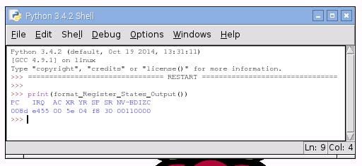
The moment of anticipation is shown in the following figure.


The output is the following:

 Memory write to address 0x1000  
 Memory read from address 0x1000  
 Read memory 0x1000 : 15  

Loading Machine Language into Memory

The classic book, Machine Language for Beginners is now online. This book was published in the early 1980s.  In chapter 3, The (Machine Language) Monitor, there is a discussion on what machine language looks like in memory and what it looks like when it is disassembled.

 2000     A9 41          LDA          #$41  
 2002     8D 23 32       STA          $3223  
 2005     A4 99          LDY          $99  

Let's take a look at this, the first line of code is at memory location, 0x2000 (8192 integer). This is called the address field. Moving over to the right is the hex value A9 (0xA9 hex or 169 integer). This is our opcode which is a representation for the instruct LDA (LoaD Accumulator). Over to the right of the opcode is the argument field, 41. Now the pound sign is in the far right, #$41, this tells the 6502 to load the value of $41 (0x41 hex  or 65 integer) into the accumulator. The next address field is 0x2002. Where we will store the value now in the accumulator register at location $3223 (0x3223 hex or 12, 835 integer). Let's load this simple machine language program into our emulated memory device. Here is MachineCodeTest.py.

1:  #-------------------------------------------------------------------------------  
2:  # Name:    MachineCodeTest.py  
3:  # Purpose:   Software driver for RAM_8bit_Memory.py  
4:  #  
5:  # Author:   Michael Norton  
6:  #  
7:  # Created:   05/18/2016  
8:  # Copyright:  Copyright: (c) Michael Norton Black Hole Computing 2016   
9:  #   
10:  #-------------------------------------------------------------------------------  
11:  # import 6502 library module  
12:  from RAM_8bit_Memory import *  
13:  def main():  
14:    pass  
15:  # Add machine language code into memory    
16:  #  
17:  # 2000     A9 41          LDA          #$41  
18:  # 2002     8D 23 32       STA          $3223  
19:  # 2005     A4 99          LDY          $99  
20:  #  
21:  # 2000     A9 41          LDA          #$41  
22:    write_mem(0x2000, 0xA9)  
23:    write_mem(0x2001, 0x41)  
24:  # 2002     8D 23 32     STA          $3223    
25:    write_mem(0x2002, 0x8D)  
26:    write_mem(0x2003, 0x23)  
27:    write_mem(0x2004, 0x32)  
28:  # 2005     A4 99          LDY          $99    
29:    write_mem(0x2005, 0xA4)  
30:    write_mem(0x2006, 0x99)  
31:  # examine memory  
32:    print ("Read memory 0x2000 : ", read_mem(0x2000))  
33:  if __name__ == '__main__':  
34:    main()  

And the desired results are pretty much what we expected.

 Memory write to address 0x2000  
 Memory write to address 0x2001  
 Memory write to address 0x2002  
 Memory write to address 0x2003  
 Memory write to address 0x2004  
 Memory write to address 0x2005  
 Memory write to address 0x2006  
 Memory read from address 0x2000  
 Read memory 0x2000 : 169  

The basic simple memory architecture is in place. It still needs some work to ensure the values stored are 8-bit value constraints and not writing 32-bit values.

The 6502 Instruction Set

I have started the ground work on a Python dictionary for the 6502 instruction set. It pretty much was created in a Microsoft Excel spreadsheet and then I manipulated it into a facsimile of a Python dictionary. It is now running and we'll tackle the instruction set or the CPU registers in the next installment of the Raspberry Pi work bench blog.  With the instruction set I can either go down the path of building a machine code disassembler, possibly a monitor, or even start crafting the cpu emulator. Happy 8-bit hacking!!!

Sunday, April 10, 2016

Setting up your wifi network on Raspberry Pi Jessie

In this blog entry  I am going to document some tasks that must be completed when Raspberry Pi boots the first time under the Jessie operating system. For this instructional I am using this release of Raspian Jessie on a Raspberry PI 2.

  No LSB modules are available.   
  Distributor ID: Debian   
  Description: Debian GNU/Linux 8.0 (jessie)   
  Release: 8.0   
  Codename: jessie   

The device boots up on its own. But under the first boot you will notice some subtle things you will need to do to make the device functional. The most obvious thing you will want to do is bring up the wifi network interface and configure the default gateway for network routing. You will need to edit some config files, which are rather simple and straight forward to modify. This will lead to one subtle and annoying thing you must edit first which has nothing to do with network configuration. The default keyboard configuration is for a UK keyboard layout. I am in the US and I found the keys, like the " and the @ symbol are swamped - among others! 

Setting the Keyboard Layout to US

My first step was to edit my default keyboard config file for a US keyboard.  To edit the deyfault keyboard file, you will need to open a terminal window on your Raspberry Pi . Type the following command from your terminal,


 sudo nano /etc/default/keyboard   


 You will need to locate setting XKBLAYOUT="uk" field in this file and change it to "us".
 

 XKBLAYOUT="us"  


To exit the nano editor, press the keys, CTRL-X. Then answer Y-yes to save the file.  

The Raspberry Pi will then need to be rebooted.

 sudo reboot  

After the system has rebooted we can proceed to setting up the wifi network.


Configuring the Wifi Network on the Raspberry Pi

My Raspberry Pi was originally running wheezy. I had a lot of wifi issues under the old operating system and I could never get my USB wifi to run properly. Under Jessie, my wifi came right up!

Open a terminal window and let's bring up your wifi. From the terminal window command line you will need go to the wifi configurations directory. We're going to edit the wpa_supplicant.conf  file.

 cd /etc/wpa_supplicant  
 sudo nano wpa_supplicant.conf  


Add the following lines to wpa_supplicant file. Note that the SSID is your wifi network name, and the psk is the password field for your wifi network.


 network={  
     SSID="MY_WIFI_NETWORK_NAME"  
     psk="my_wifi_network_password"  
 }  

To exit the nano editor, press the keys, CTRL-X. Then answer Y-yes to save the file.  

A true unix administrator would bring up the network interface rather than reboot. I could not get my wifi network to reset with the commands,


 sudo ifdown wlan0  
 sudo ifup wlan0  

I opted for the complete device reboot. 

 sudo reboot  

When the device reboot is completed you should be able to ping the address of your default gateway router (your wifi).

Configuring the Default Gateway

Now we have a wifi network, but you probably noticed your web browser doesn't work. What happened?

The default gateway is not configured on the Raspberry Pi. The Raspberry Pi is confined to accessing only devices that are on the same network subnet.

This is not straight forward in Raspian OS. I initially tried simply configuring the default gateway from the terminal window with the command route add,  where the gateway address on my network is 10.0.0.1.
     
 sudo route add default gw 10.0.0.1  

This worked fine until I rebooted my Raspberry Pi and I lost my network default gateway. I wanted a permanent solution. Of course the solution is not so obvious, but here is what I found googling for an answer. Let the device determine the default gateway! 

You will need to edit your /etc/network/interfaces file from a terminal window.

 sudo nano /etc/network/interfaces  

Add the following configuration to this file,

 auto eth0

To exit the nano editor, press the keys, CTRL-X. Then answer Y-yes to save the file.   

And of course - reboot!

 sudo reboot  


 By now you should have usable internet connection to start configuring the rest of your Raspberry Pi. Hope this helps you in bringing up your Raspberry Pi.